Remote monitoring/control of small installations
Solutions with 7bit & Level2Let’s say you have a small engineering system, such as a boiler room or boiler, individual heating station, uninterruptible power supply system, etc. that works perfectly on its own, but you want to have remote access to control this system in order to change the operating mode, switch it off/on. You can also do much more – get analytics on equipment operation, event logs, error messages, etc.
As a rule, all modern automation has an interface to a control or dispatching system. All you need to do is to install one of our gateways (there are several options, you can even use your own version if it supports the MQTT data exchange protocol) and connect it to the Level2 cloud service, and then configure the functions you need for monitoring – a visualisation screen, if necessary, parameter archiving, etc.
Let’s take a closer look at these steps.
Connecting to equipment
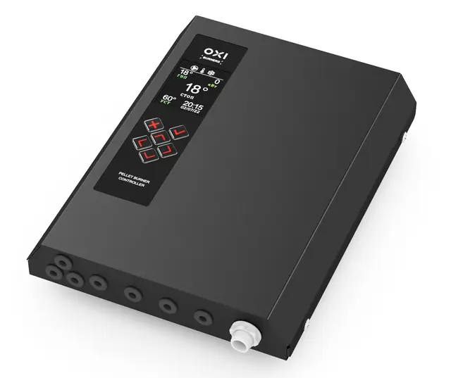
Here is an example of how to connect to the OXI pellet boiler controller The controller looks like this:
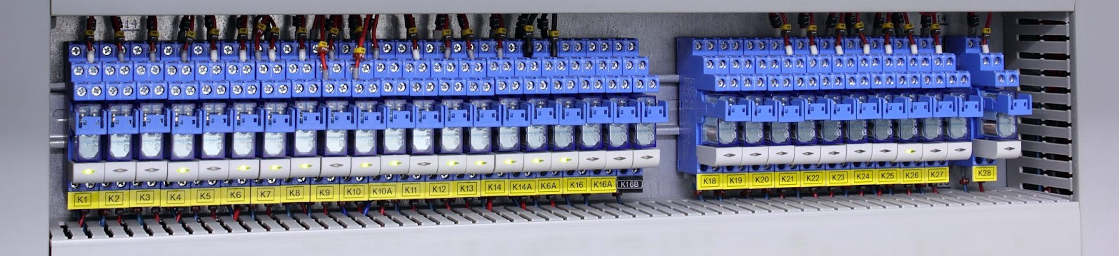
Under the cover is the control board, to which you need to find the interface for connection, usually RS-485. Its terminals may have the following or similar names, examples of which are given in the table:
| Vendor | Positive terminal | Negarive terminal |
| Texas Instruments | В | А |
| Schneider Electric | D1 | D0 |
| Siemens, Advantech | D+ | D- |
| Moxa | TXD+ | TXD- |
| Phoenix Contact | B | A |
| National Instruments | DI+ | DI- |
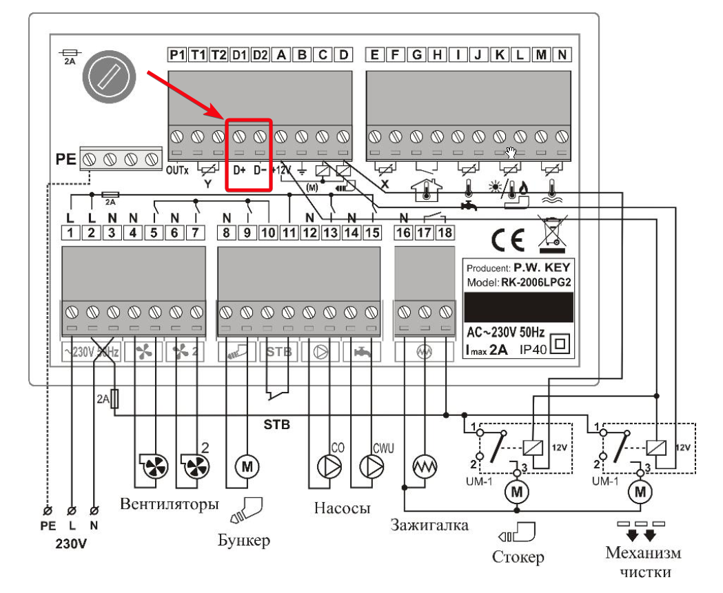
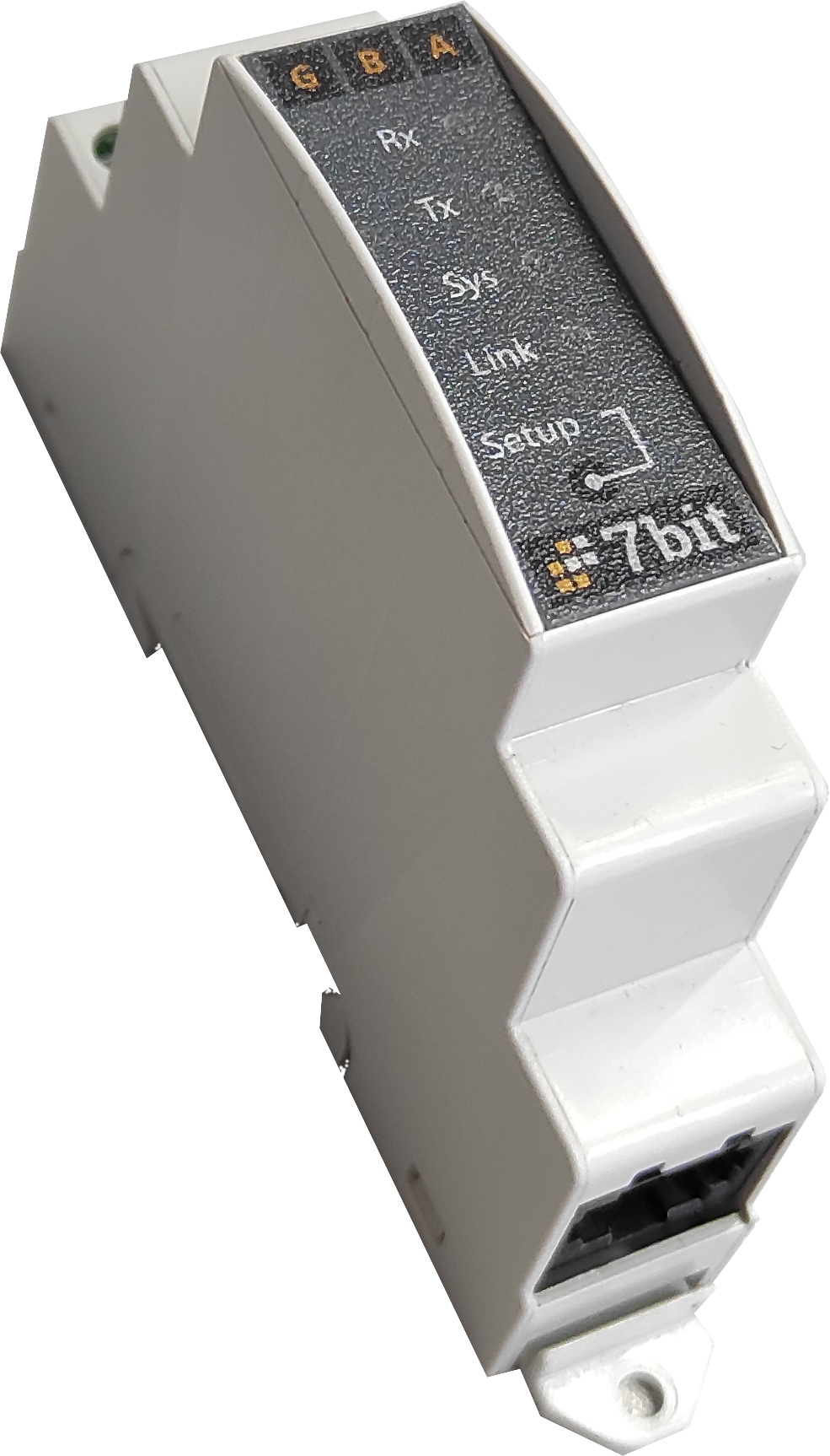
The D+, D- terminals are connected to the A, B terminals of the 7bit CloudPoint gateway, respectively:
Setting up communication between the gateway and the controller
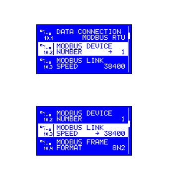
The serial port settings can be found in the menu of the controller itself:
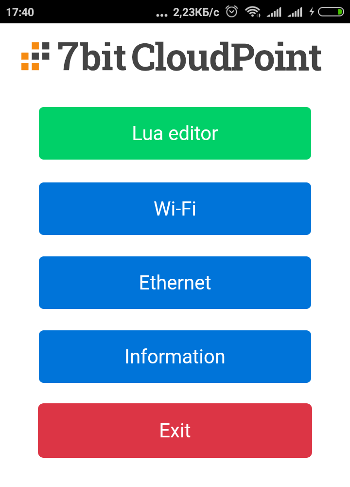
These parameters must be specified in the gateway program. To enter the programming mode, click the Setup button on the gateway. The gateway will enter the configuration mode and its configuration page will become available (it can be accessed either via an Ethernet connection or via an access point created by the module during configuration, the SSID is 7bitLuaXXXXXX, the password for connection is 12345678).
You need to find this line in the program and correct it if necessary:
uart.attach(PORT, 38400, 8, uart.PARNONE, uart.STOP2) Here:
- 8 – data bit number(8)
- 38400 – speed
- uart.PARNONE – constant that says no parity control is used
- uart.STOP2 – constant that says no we use 2 stop bits
Reading the required parameters from the controller
All controller parameters have specific addresses in the memory, which can be read via the Modbus RTU protocol. As a rule, this information is provided in the user manual for the device, or can be downloaded from the download section of the manufacturer’s website (if you cannot find the map or have questions about connection, please contact our technical department). For example, the controller parameter map may look like this:
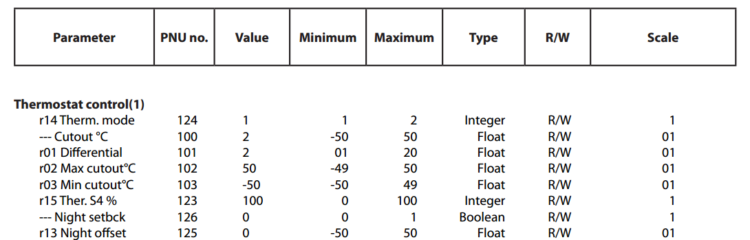
PNO no. – is the address of the register in the memory, type is the type of data contained in the register, scale is the multiplier by which the data in the register must be multiplied to obtain the actual value.
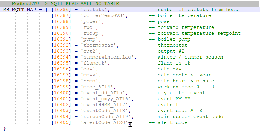
The gateway application has two tables that it uses to read or write data. One table is for reading, the other is for writing. That is, the gateway periodically reads the registers in the table, generates a JSON packet with the names of the parameters (or “keys” by which they will be in the packet) and their values, and sends this packet via the MQTT protocol to the Level2 server. Conversely, every time a variable in the structure is changed to a record (or “topic” in MQTT terminology) on the server, the gateway uses a similar table to determine which register the value should be written to.
Setting up to connect the 7bit CloudPoint gateway to Level2
Setting up your Level2 account
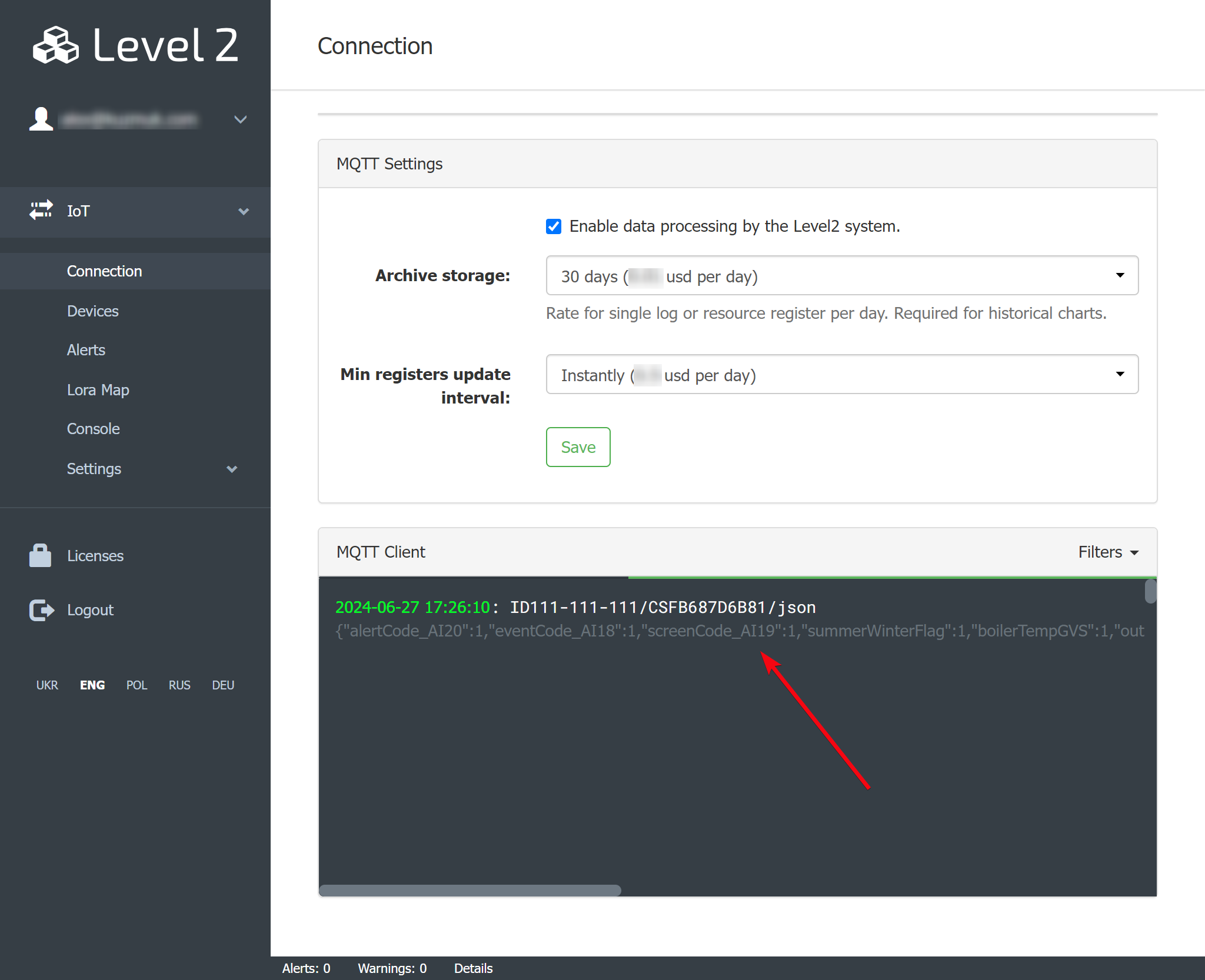
STEP 1: Enable MQTT data processing in the cabinet: (Enable checkbox)
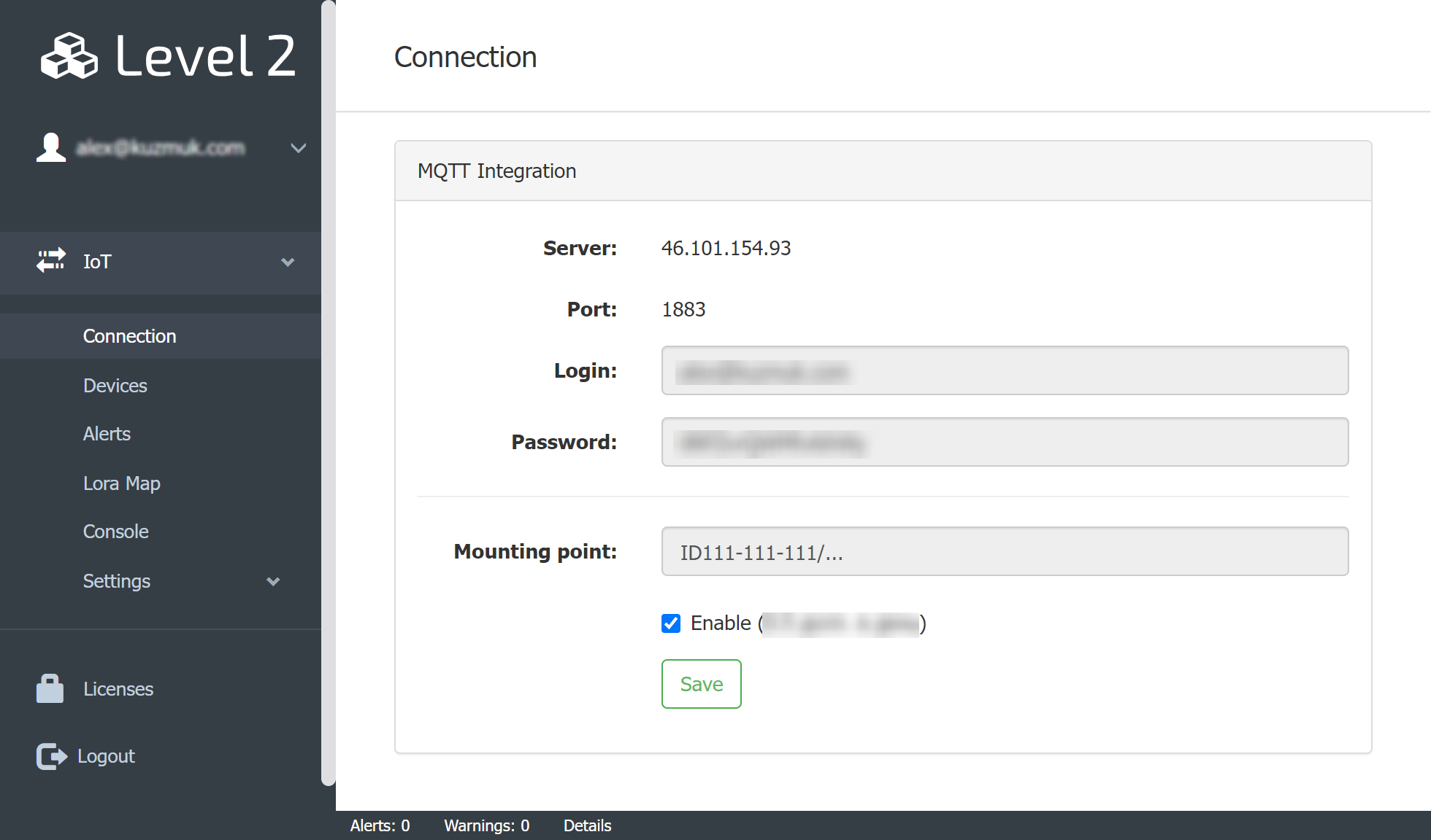
This data will need to be entered in the gateway application.
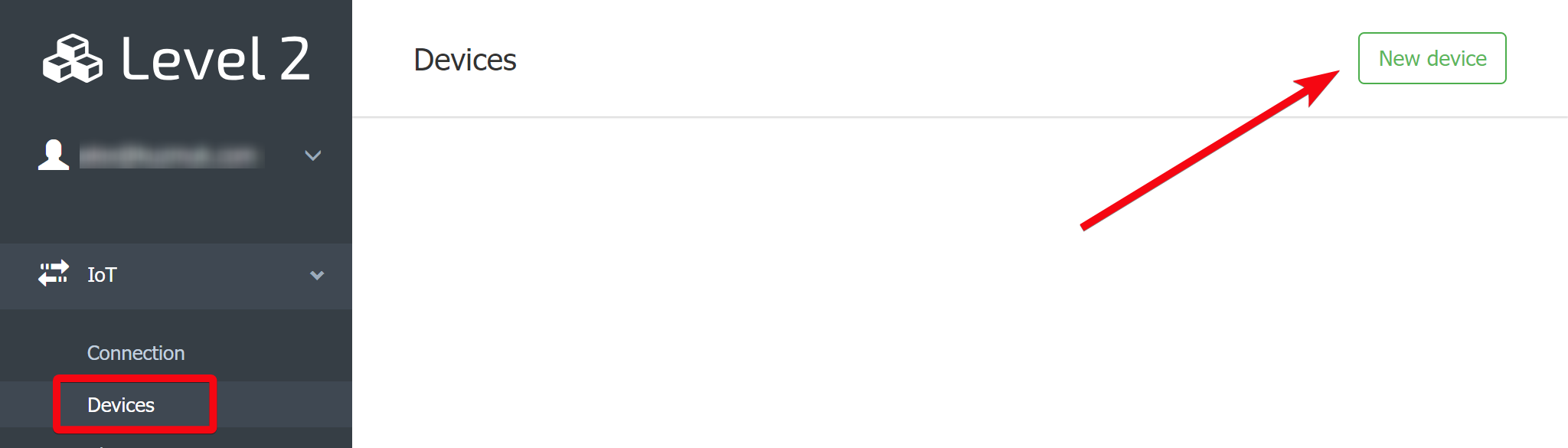
STEP 2. Add an IoT device
Press the New device button.
Add a Custom device, and don’t forget to tick the Activation checkbox:
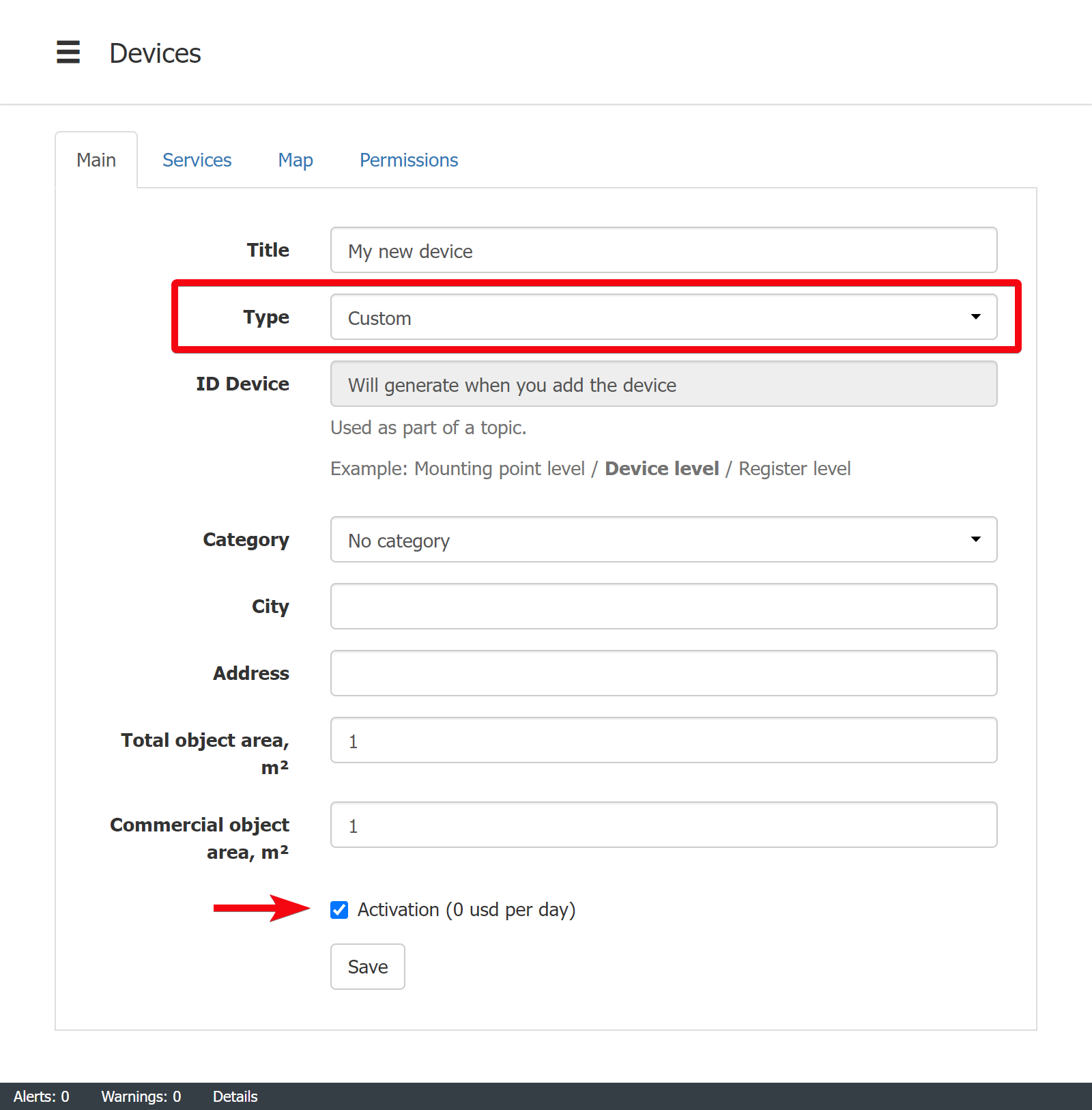
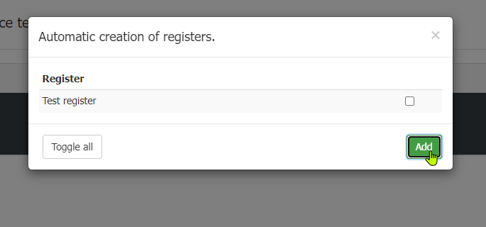
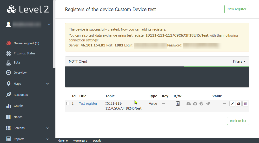
When you create a device, the system also suggests adding a test tag, which you can then edit as needed (see below).
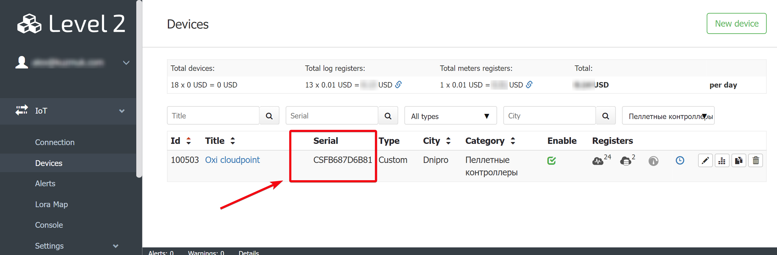
The system creates the device (node) and generates a valid ID for it. This Device ID must also be specified as part of the parameter (topic) address in the gateway application.
How MQTT data is processed in Level2
In order for data to appear in a particular user account, the top (the name of the variable transmitted in MQTT terminology) must comply with a specific format:
<Mounting point>/<Device ID>/<name>
Mounting point
Using the mount point, the data is filtered for a specific office in Level2.
Device ID (Serial)
This part of the topic defines which device or node the data came from.
name
The name finally specifies the parameter to be sent. For example, it could be fwd, analog_input1, etc. The token can be simple (if it contains a single value) or complex – a json structure in the form of a string. In the latter case, the values of the parameters are selected by their “keys”. Usually, it is more convenient to send structured data in one package, in our example it will be json, then the entire top will look like this:
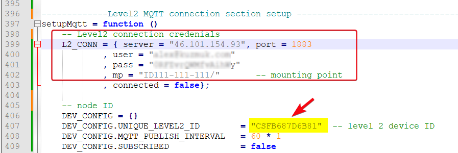
ID111-111-111/CSFB687D6B81/json
Settings in the gateway app
You need to specify the above connection details in the gateway application:
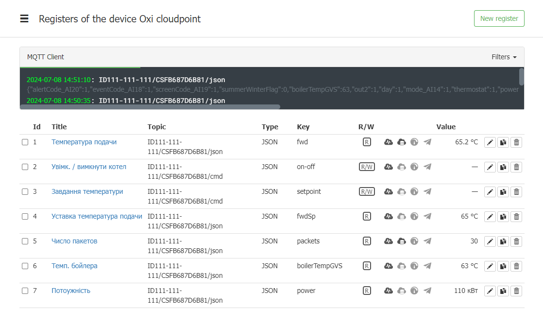
Checking data reception in the console
There is a debugging console in the user account, you need to check that the data is coming in:
Setting up the received data in Level2
After the data is successfully sent from the gateway, you need to configure individual parameters or variables. Then they can be used in visualisation, archiving, etc.
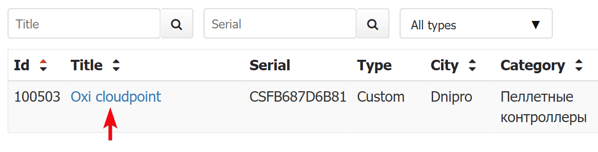
For example, we want to create a tag with the supply temperature. In the gateway application, it is named fwd. When you created the device, one tag was already created, so you can simply edit it. To go to the list of device tags, just click on its name in the device list, it is a link at the same time.
You will be taken to the page of registers (tags) of the device. We will see that the system now has one register of a simple type (just a value, without specifying a key).
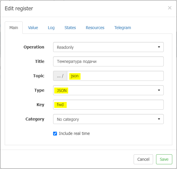
You need to indicate that it is a complex case (JSON), specify the last part of the top (json) and the key (fwd):
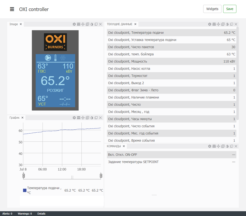
The parameters are now available and can be used in Level2 monitoring system components, such as:
- gpaphs
- screens
- maps
- reports on resource consumption